Marking and layout
Transfer a layout with a story stick
Carry three unequal positions onto two matching parts without measuring each interval again.
Materials and practice dimensions
- One straight scrap strip, about 300 × 25 × 6 mm, for the master
- Two practice strips, about 300 × 50 mm; thickness is unimportant for this marking exercise
- Ruler, checked square, sharp pencil and removable labels
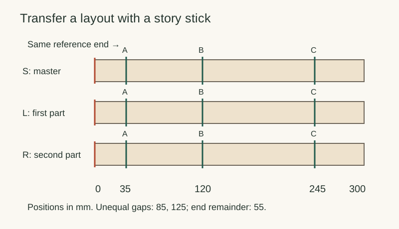
This example transfers positions at 35, 120 and 245 mm from one end. They are deliberately unequal so a reversed master is easy to spot. These are layout marks only; they do not specify safe screw distances, drilling sizes or a joint.
Work through the procedure
1. Name the parts and origin
Label the master S and the two receiving parts L and R. On each, mark the reference end with a large zero and draw an arrow toward the far end. Mark the face that must remain visible during transfer.
2. Make the master once
Measure 35, 120 and 245 mm directly from zero on S. Extend each fine mark across its width with the square. Label them A, B and C. Check the three absolute measurements independently before copying anything.
3. Transfer to the first part
Lay S beside L with the zero ends flush and arrows pointing the same way. Bring the pencil to each master line and make a tick on L. Remove S, then extend the ticks across L using its chosen reference edge.
4. Transfer to the second part
Repeat on R using the same face and origin convention. Do not turn the master end for end to make it easier to hold. If your actual design calls for mirrored parts, define its reference ends explicitly before marking.
5. Compare the pair
Align the zero ends of L and R beside one another. A should match A, B should match B, and C should match C. Recheck the 35 mm first position and the 55 mm remaining distance after C. Keep S with the project until the layout is accepted.
Worked example
The gaps between the example marks are 85 mm and 125 mm; the far end is 55 mm beyond C. Measuring every gap in sequence can carry one error forward. A story stick preserves one verified layout, but also repeats any mistake in that master. Reversing this master would put the marks at 55, 180 and 265 mm from the receiving zero.
Check the result
- Master positions are checked before they are copied.
- Both receiving parts show the same zero, face and arrow convention.
- All corresponding lines coincide when the zero ends align; the 55 mm end remainder is confirmed.
If it does not work
If all marks shift by the same amount, check the flush zero ends. If the order is reversed, erase or clearly cancel the wrong set before re-marking. If only one line differs, return to its original master mark rather than averaging two conflicting positions.
Keep a workshop record
Use the downloadable worksheet or print this page and write beside each prompt.
Master identifier and reference face: ____________________
A / B / C positions from zero: ____________________
Independent check of master: ____________________
L and R comparison: ____________________
End remainder: ____________________
Cancelled marks / correction: ____________________
Continue your work
Sources and method
The practice dimensions, examples and diagrams are original. Manufacturer guidance is scoped to the named products. Review the current product instructions before using them. Sources checked October 20, 2026.
- Woodpeckers: Story Stick Pro 96 — Description and reference-marking introduction.